WELCOME TO RIVER DAVES PLACE

Mach 26 hydraulic steering

mattyc

Well-Known Member
Joined
Sep 9, 2017
Messages
425
Reaction score
492
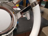
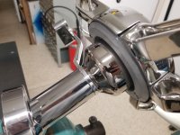
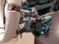
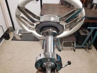
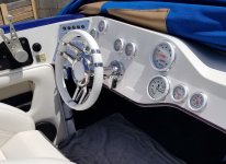
Hey guys, I'll apologize in advance for being long winded. The boat has a two ram add on kit and I'm finally getting around to upgrading to full hydraulic. The biggest problem I've needed to sort out is how to deal with the trim control. Currently, trim switch is mounted on the steering wheel, which we've come to like except for when you need to make a trim adjustment and the wheel is half turned so the switch is upside down and backward. Bare with me, more to come, and I dont think it will disappoint. Thanks for reading
 

Attachments

  • 20230917_115833.jpg
    20230917_115833.jpg
    2.6 MB · Views: 59
Last edited:

mattyc

Well-Known Member
Joined
Sep 9, 2017
Messages
425
Reaction score
492
Obviously I could move it over to the throttle. I could modify my existing throttle or put in one of those fancy dana units. Believe me, I've struggled with this. I like the side mount controls we have and I didnt want to put in a new unit that doesnt have the same base plate. Plus cost is a consideration for us. Kicked around some other ideas as well. Didnt want to add pedals because weve come to enjoy the clean flat floor. We really wanted to keep the trim up on the steering somehow. We looked at the blinker switch style but they just didnt have the right look. Oh, and a dangly cord was not an option. This is the only picture I have with the side mount in it, haha you'll just have to look past the ole lady
 

Attachments

  • 20230702_111123.jpg
    20230702_111123.jpg
    4.6 MB · Views: 141

mattyc

Well-Known Member
Joined
Sep 9, 2017
Messages
425
Reaction score
492
I picked up a real nice tilt column I wanted to use. I took it apart to see what I was dealing with and after considerable staring, pondering and measuring, I had a plausible solution for routing wiring through this thing.
 

Attachments

  • 20240224_142721.jpg
    20240224_142721.jpg
    1.5 MB · Views: 59

mattyc

Well-Known Member
Joined
Sep 9, 2017
Messages
425
Reaction score
492
I decided to mount the trim switch to the fixed portion of the steering post rather than trying to have it on the wheel. I determined that the post had enough wall thickness to run the wires in a recess on the outside of the bearing diameter. I measured the current draw on the trim pump relays and picked out a wire with the smallest outside diameter that would safely carry the load; a 24 gauge mil spec wire. I also tested the wire with a high beam bulb for 10 minutes continuous to make sure the wire would do the job. I set the post up on the rotary table and machined a recess behind both bearings deep enough to accommodate the wires. I did it with the rotary table in order to create a radiused recess that matches the post rather than a square recess that ends up deeper on the ends than needed.
 

Attachments

  • 20240224_153405.jpg
    20240224_153405.jpg
    1.4 MB · Views: 72
  • 20240224_161410.jpg
    20240224_161410.jpg
    1.6 MB · Views: 73
  • 20240224_162205.jpg
    20240224_162205.jpg
    2.7 MB · Views: 68
  • 20240224_191826.jpg
    20240224_191826.jpg
    1.1 MB · Views: 69
  • 20240224_192305.jpg
    20240224_192305.jpg
    1.3 MB · Views: 70
  • 20240224_163107.jpg
    20240224_163107.jpg
    2.9 MB · Views: 74

mattyc

Well-Known Member
Joined
Sep 9, 2017
Messages
425
Reaction score
492
I got a pair of the switches from marine industries west that they use in their throttle assemblies. I drew up a switch housing to accommodate the switches with room to install and attach wiring. I started by squaring up a small block of aluminum using a method @Toolman showed me. Then I drilled and tapped the 6-32 mounting holes. I started hogging out the center by drilling holes for the corners. No digitals at my place so I set my boundaries with hard stops for x and marking the ways in y with the number corresponding to the dial. My y locations are all set using clockwise dial rotation. I drilled a bunch of holes in the middle just to remove material, then switched to an end mill to finish the opening. I flipped the block and poked holes for the switches then finished the hole diameter with a boring head since the switch bodies were an odd size. A couple more flips and a corner rounding end mill to radius the corners. Thanks for following, next item is the bracket to hold the switch housing.
 

Attachments

  • 20240225_171249.jpg
    20240225_171249.jpg
    2.6 MB · Views: 76
  • 20240225_171226.jpg
    20240225_171226.jpg
    2.6 MB · Views: 73
  • 20240225_153649.jpg
    20240225_153649.jpg
    3.7 MB · Views: 68
  • 20240225_150532.jpg
    20240225_150532.jpg
    2.5 MB · Views: 66
  • 20240225_134626.jpg
    20240225_134626.jpg
    3.5 MB · Views: 69
  • 20240225_133433.jpg
    20240225_133433.jpg
    3.1 MB · Views: 68
  • 20240225_133427.jpg
    20240225_133427.jpg
    3.1 MB · Views: 64
  • 20240225_124541.jpg
    20240225_124541.jpg
    3.4 MB · Views: 65
  • 20240225_120948.jpg
    20240225_120948.jpg
    3 MB · Views: 64
  • 20240225_114510.jpg
    20240225_114510.jpg
    3.5 MB · Views: 67
  • 20240225_104738.jpg
    20240225_104738.jpg
    3.6 MB · Views: 71

Nanu/Nanu

Don't wait til' life's easy to be happy
Joined
Jul 30, 2020
Messages
2,673
Reaction score
4,786
Damn dude nice work!

If this doesn't work out have you looked at @ChrisV dcb thread? He just showed off a set of paddle shifters for trim adjustment.
 

Jay Dub

Well-Known Member
Joined
Jun 11, 2020
Messages
1,138
Reaction score
1,272
I got a pair of the switches from marine industries west that they use in their throttle assemblies. I drew up a switch housing to accommodate the switches with room to install and attach wiring. I started by squaring up a small block of aluminum using a method @Toolman showed me. Then I drilled and tapped the 6-32 mounting holes. I started hogging out the center by drilling holes for the corners. No digitals at my place so I set my boundaries with hard stops for x and marking the ways in y with the number corresponding to the dial. My y locations are all set using clockwise dial rotation. I drilled a bunch of holes in the middle just to remove material, then switched to an end mill to finish the opening. I flipped the block and poked holes for the switches then finished the hole diameter with a boring head since the switch bodies were an odd size. A couple more flips and a corner rounding end mill to radius the corners. Thanks for following, next item is the bracket to hold the switch housing.
damn, nice work
 

mattyc

Well-Known Member
Joined
Sep 9, 2017
Messages
425
Reaction score
492
Damn dude nice work!

If this doesn't work out have you looked at @ChrisV dcb thread? He just showed off a set of paddle shifters for trim adjustment.
Thanks! I have seen the paddles. I'm not crazy about dual paddles since it requires two hands but I did see a single paddle somewhere with up and down. Some of those options, in my opinion dont fit the era and styling of this boat. A lot of my projects are also about challenging myself I guess
 

mattyc

Well-Known Member
Joined
Sep 9, 2017
Messages
425
Reaction score
492
So the next piece of the puzzle is a bracket that will position my switch housing within comfortable reach behind the steering wheel. Sort of a blinker or paddle deal, but different. I mocked it up with cardboard and had the wife try it out for feel since she drives the boat a lot too. I drew it up and clamped the material in a way that would allow the majority of work to be done in one holding. I started by drilling a center which I called my zero position. This will represent the center of the steering shaft and be my start point for all other operations. Next I bored four 1" holes to create the 1/2" radii I thought would look nice. More holes for material removal and machined the sides. Drilled and counterbored two holes for the 6-32s that will hold the switch housing. Using the center i drilled in the beginning to locate the bracket in the rotary table, I machined the circle on the end. Back to the vice to machine the 5/16" radii to match the switch housing. I clamped it on its face and machined a groove that the wiring will press into.
 

Attachments

  • 20240302_090306.jpg
    20240302_090306.jpg
    3 MB · Views: 58
  • 20240302_103814.jpg
    20240302_103814.jpg
    3.5 MB · Views: 51
  • 20240302_120907.jpg
    20240302_120907.jpg
    3.7 MB · Views: 52
  • 20240302_133409.jpg
    20240302_133409.jpg
    1.6 MB · Views: 48
  • 20240302_171908.jpg
    20240302_171908.jpg
    3.4 MB · Views: 51
  • 20240303_091609.jpg
    20240303_091609.jpg
    3.4 MB · Views: 54
  • 20240303_143703.jpg
    20240303_143703.jpg
    3.9 MB · Views: 56

Nanu/Nanu

Don't wait til' life's easy to be happy
Joined
Jul 30, 2020
Messages
2,673
Reaction score
4,786
Thats so awesome you have the knowledge to do this kind of stuff
 

mattyc

Well-Known Member
Joined
Sep 9, 2017
Messages
425
Reaction score
492
The bracket will be attached to the post using three counterbored 6-32 socket head cap screws. I made up a bar that I indicated and straightened in v blocks. The bar slides through the hinge pin holes in the bottom of the post. It will serve as something to clamp and also give me a straight line to reference and indicate the hinge axis parallel with x. This way my hole patterns will match and the bracket will come off the post parallel to the hinge when everything is assembled. I clamped it and indicated it in on the rotary table. My hole patterns are made using a bolt circle I designated that puts the holes center in the wall on the post. 120 degrees between holes.
 

Attachments

  • 20240330_101013.jpg
    20240330_101013.jpg
    2.9 MB · Views: 46
  • 20240330_134117.jpg
    20240330_134117.jpg
    3.8 MB · Views: 43
  • 20240330_144226.jpg
    20240330_144226.jpg
    1.1 MB · Views: 45
  • 20240330_150203.jpg
    20240330_150203.jpg
    2.3 MB · Views: 44
  • 20240330_150332.jpg
    20240330_150332.jpg
    2.6 MB · Views: 43

HAP

Well-Known Member
Joined
Apr 2, 2017
Messages
84
Reaction score
50
I ended up making a trim switch grip for my throttle when I went hyd steer. I did try mounting to the wheel at first and learned really quick why the trim switch instructions said not for Hyd Helms. I then wanted a symmetrical steering wheel so it would not be that noticeable as it crept around.
Nothing even close to your results.
R,
HAP
IMG_2904.jpg
IMG_2905.jpg
IMG_2908.jpg
IMG_2909.jpg
 
Last edited:

mattyc

Well-Known Member
Joined
Sep 9, 2017
Messages
425
Reaction score
492
After making sure my mounting holes actually lined up, the bracket needed two bends to locate the switch where I wanted it. Using a v block, an edge attachment and some copper backing, I made the bends in the press. I just whiskey eyed it against my angle gauge then rough assembled it to make sure it was coming together as planned.
 

Attachments

  • 20240330_164813.jpg
    20240330_164813.jpg
    3.5 MB · Views: 64
  • 20240330_170725.jpg
    20240330_170725.jpg
    3 MB · Views: 65
  • 20240403_123728.jpg
    20240403_123728.jpg
    2.1 MB · Views: 65

lenmann

Well-Known Member
Joined
Apr 13, 2013
Messages
1,660
Reaction score
3,330
I’m loving the detail in your posts on how you are doing this stuff, it’s cool to see the fab approach and the end product. Nicely done sir.
 

mattyc

Well-Known Member
Joined
Sep 9, 2017
Messages
425
Reaction score
492
I’m loving the detail in your posts on how you are doing this stuff, it’s cool to see the fab approach and the end product. Nicely done sir.
Thanks! There's a lot of talent around here, I'm just trying to fit in
 

mattyc

Well-Known Member
Joined
Sep 9, 2017
Messages
425
Reaction score
492
After a bit of deburring and polishing, I could assemble everything. I ran the wires and placed them in their recess then installed the shaft and lower bearing. This assembly came with spiral wound retaining rings so I had to replace the lower one with a traditional snap ring so it wouldnt interfere with the wiring. I ran the wires through a heat shrink tube and soldered the connections to the switches. Originally I was going to make the connections at the switches, then install them in the housing but I couldnt get enough grip on the nut to make that work so it was easier to hold the nut and spin the switch in. Before going further, I load tested my circuits with a high beam test light I made up for work. The bulb draws 4 amps, trim pump relays draw about 1 1/2 amps when I measured. After verifying my connections were good, I shrunk the tubing and pulled the slack back out the other end. Mount the switch housing to the bracket and press the wiring into place in its groove. I situated the wires in the post and attached the bracket. Because of the added plate, i had to turn the back face of the steering wheel adapter down, about .200". I used letter stamps for the label. I clamped the four stamps together and let the shanks take care of the spacing. Did a couple test stamps in the press and noted the pressure applied to get the result I wanted. I debated on setting this up in the rotary table to do the lettering but decided it wasnt worth another two weekends lol. I'm very happy with how it turned out. Next I have to get in the boat and install this. Thanks for following
 

Attachments

  • 20240405_062313.jpg
    20240405_062313.jpg
    3 MB · Views: 87
  • 20240405_062226.jpg
    20240405_062226.jpg
    3.1 MB · Views: 87
  • 20240405_062252.jpg
    20240405_062252.jpg
    3 MB · Views: 86
  • 20240405_062201.jpg
    20240405_062201.jpg
    3.1 MB · Views: 83
  • 20240405_062122.jpg
    20240405_062122.jpg
    3.1 MB · Views: 81
  • 20240405_062104.jpg
    20240405_062104.jpg
    3.3 MB · Views: 79
  • 20240404_180956.jpg
    20240404_180956.jpg
    3.5 MB · Views: 76
  • 20240404_074502.jpg
    20240404_074502.jpg
    3.6 MB · Views: 75
  • 20240331_161129.jpg
    20240331_161129.jpg
    1.3 MB · Views: 70
  • 20240331_151809.jpg
    20240331_151809.jpg
    2.9 MB · Views: 69
  • 20240331_151801.jpg
    20240331_151801.jpg
    3.1 MB · Views: 64
  • 20240331_150035.jpg
    20240331_150035.jpg
    2.9 MB · Views: 66
  • 20240331_140839.jpg
    20240331_140839.jpg
    1.2 MB · Views: 59
  • 20240331_140703.jpg
    20240331_140703.jpg
    1.2 MB · Views: 60
  • 20240331_135652.jpg
    20240331_135652.jpg
    1.2 MB · Views: 62
  • 20240331_134644.jpg
    20240331_134644.jpg
    3.5 MB · Views: 73

mattyc

Well-Known Member
Joined
Sep 9, 2017
Messages
425
Reaction score
492
Been very busy lately so progress has been slow. The tilt post came with an aluminum spacer which I found out was too thin for my setup so I machined my own spacer from a big chunk of delrin I had. Added a female pilot on the helm side and another channel for wiring to pass through. I decided to use the included aluminum spacer as a drill guide and machined a plastic pilot to center it over the existing hole in the dash. Got it assembled and wiring connected. Next I need to pull some interior and take out the cable and stock steering actuator. I will be making a mount for the new imco filter that will put it in place of the actuator.
 

Attachments

  • 20240427_085210.jpg
    20240427_085210.jpg
    2.9 MB · Views: 70
  • 20240427_085203.jpg
    20240427_085203.jpg
    2.9 MB · Views: 65
  • 20240406_180201.jpg
    20240406_180201.jpg
    3.2 MB · Views: 58
  • 20240427_100442.jpg
    20240427_100442.jpg
    3.1 MB · Views: 62
  • 20240505_162032.jpg
    20240505_162032.jpg
    3.3 MB · Views: 65
  • 20240505_162039.jpg
    20240505_162039.jpg
    3.4 MB · Views: 73
  • 20240505_162130.jpg
    20240505_162130.jpg
    3 MB · Views: 71
  • 20240505_162120.jpg
    20240505_162120.jpg
    3.7 MB · Views: 70
  • 20240427_134814.jpg
    20240427_134814.jpg
    3.4 MB · Views: 69
  • 20240427_134821.jpg
    20240427_134821.jpg
    3.3 MB · Views: 70
  • 20240503_124038.jpg
    20240503_124038.jpg
    2 MB · Views: 70

ChrisV

Well-Known Member
Joined
Nov 30, 2020
Messages
3,526
Reaction score
10,589
Beautiful man! Dope to see your wife hanging out with your kid on the boat too.
 

mattyc

Well-Known Member
Joined
Sep 9, 2017
Messages
425
Reaction score
492
Beautiful man! Dope to see your wife hanging out with your kid on the boat too.
Thank you! Damn you're really observant, I didnt even realize they were in the picture. He was two weeks old on saturday, was going to do a new member introduction, guess I better get on it
 

ChrisV

Well-Known Member
Joined
Nov 30, 2020
Messages
3,526
Reaction score
10,589
Thank you! Damn you're really observant, I didnt even realize they were in the picture. He was two weeks old on saturday, was going to do a new member introduction, guess I better get on it
Congrats! It's a problem i hate sometimes.

Are you planning to do anything with the shifter plate? The black really throws it off. I only ask because I have the same one.
 

mattyc

Well-Known Member
Joined
Sep 9, 2017
Messages
425
Reaction score
492
Congrats! It's a problem i hate sometimes.

Are you planning to do anything with the shifter plate? The black really throws it off. I only ask because I have the same one.
Thank you!

Originally, I had no intentions of messing with the shifter but after seeing the post and wheel in the boat my wife and I agreed the shifter doesnt look right. I'll have to think about it. I dont want to replace it, so I may tear it down and refinish it. I like the combination of polished with clear anodized, so likely that route. I'm not sure what material the base plate is. Open to suggestions though....
 

ChrisV

Well-Known Member
Joined
Nov 30, 2020
Messages
3,526
Reaction score
10,589
Thank you!

Originally, I had no intentions of messing with the shifter but after seeing the post and wheel in the boat my wife and I agreed the shifter doesnt look right. I'll have to think about it. I dont want to replace it, so I may tear it down and refinish it. I like the combination of polished with clear anodized, so likely that route. I'm not sure what material the base plate is. Open to suggestions though....
I would say brush aluminum or polished stainless. When my boat comes back i'm take it apart and see what i can do and let you know.
 

mattyc

Well-Known Member
Joined
Sep 9, 2017
Messages
425
Reaction score
492
A little more progress. I decided to mount imcos filter in place of where the stock steering actuator is on the gimble. Made up a bracket that mounts the same way and got that installed along with the pressure hose from the pump to filter. A little bit at a time.
 

Attachments

  • 20240518_160056.jpg
    20240518_160056.jpg
    2.6 MB · Views: 31
  • 20240518_160114.jpg
    20240518_160114.jpg
    2.9 MB · Views: 28
  • 20240518_160900.jpg
    20240518_160900.jpg
    2.6 MB · Views: 33
  • 20240518_160916.jpg
    20240518_160916.jpg
    2.5 MB · Views: 35
  • 20240519_130646.jpg
    20240519_130646.jpg
    3.4 MB · Views: 32
  • 20240519_130707.jpg
    20240519_130707.jpg
    3.3 MB · Views: 32

pbleckert

Member
Joined
Apr 19, 2021
Messages
7
Reaction score
10
May I ask what helm you went with? I’m guessing that’s the imco 7.125” tilt? I have a Mach26 with an old tilt I can’t find any info on, that needs to be rebuilt or replaced. Any info would be greatly appreciated.
IMG_3765.png

IMG_4089.jpeg
 

mattyc

Well-Known Member
Joined
Sep 9, 2017
Messages
425
Reaction score
492
May I ask what helm you went with? I’m guessing that’s the imco 7.125” tilt? I have a Mach26 with an old tilt I can’t find any info on, that needs to be rebuilt or replaced. Any info would be greatly appreciated. View attachment 1377325
View attachment 1377326
The helm, filter and hoses came from imco. I actually picked up the steering post awhile back. I believe it's a Zeiger unit. I got it from eliminator, I believe they were using Zeiger products for a short time then parted ways because the company is east coast and availability was spotty. Anyway, this post is very close to 7 1/8", I dont remember the exact length, and very similar to the imco tilt post. Imco uses studs in their base plate and mounts the helm on the studs with an adapter plate while the zeiger uses socket heads cap screws that thread into the helm. Imco's stuff is very nice and would be a great upgrade for you. I've seen the one you have but I dont know anything about them. If you wanted to replace it with an imco unit, it should be compatible with your helm and will likely only need the adapter plate that imco uses. Otherwise, if you wanted to try and rebuild, I doubt there are service kits available. It would likely be something that you have to commit to taking it apart and sourcing / making parts yourself. Happy to help if i can. Was this Ricky's boat? ( i think it was Ricky ) I believe you and I talked at the sandbar a year or two ago
 

pbleckert

Member
Joined
Apr 19, 2021
Messages
7
Reaction score
10
The helm, filter and hoses came from imco. I actually picked up the steering post awhile back. I believe it's a Zeiger unit. I got it from eliminator, I believe they were using Zeiger products for a short time then parted ways because the company is east coast and availability was spotty. Anyway, this post is very close to 7 1/8", I dont remember the exact length, and very similar to the imco tilt post. Imco uses studs in their base plate and mounts the helm on the studs with an adapter plate while the zeiger uses socket heads cap screws that thread into the helm. Imco's stuff is very nice and would be a great upgrade for you. I've seen the one you have but I dont know anything about them. If you wanted to replace it with an imco unit, it should be compatible with your helm and will likely only need the adapter plate that imco uses. Otherwise, if you wanted to try and rebuild, I doubt there are service kits available. It would likely be something that you have to commit to taking it apart and sourcing / making parts yourself. Happy to help if i can. Was this Ricky's boat? ( i think it was Ricky ) I believe you and I talked at the sandbar a year or two ago
Thank you for the knowledge! The rubber boot says imco I believe, but I cant find it anywhere. Im guessing its just obsolete. I was hoping for an alternative to paying 1400 for the new imco, but that's being a boat owner I guess. My dash has taps in it to bolt it down, is yours the same or is that why you had to use the adapter on the backside? Awesome machining by the way.

And yes! small sandbar above the main sandbar, right? That would be me. You made me really want to put a whipple on my 525, but the wife seems to think the boat goes fast enough how it is. ha I disagree. Maybe next year.
 

mattyc

Well-Known Member
Joined
Sep 9, 2017
Messages
425
Reaction score
492
Thank you for the knowledge! The rubber boot says imco I believe, but I cant find it anywhere. Im guessing its just obsolete. I was hoping for an alternative to paying 1400 for the new imco, but that's being a boat owner I guess. My dash has taps in it to bolt it down, is yours the same or is that why you had to use the adapter on the backside? Awesome machining by the way.

And yes! small sandbar above the main sandbar, right? That would be me. You made me really want to put a whipple on my 525, but the wife seems to think the boat goes fast enough how it is. ha I disagree. Maybe next year.
Well you screwed up by telling her that it will make the boat faster, what the whipple ACTUALLY does is make it more reliable 😉

It's not really an adapter on mine, it's a spacer. The length of the steering shaft below the u joint makes a spacer necessary, not sure why it's that long. The socket head cap screws you see on the steering wheel side go through the dash and spacer and thread into the helm.

What is your concern with what you have? Looseness? Do you need tilt? Imco's fixed posts are just as nice and you can get one with an angled base if you dont want it 90 degrees to the dash. I imagine the fixed posts are less expensive than a tilt unit
 

ChrisV

Well-Known Member
Joined
Nov 30, 2020
Messages
3,526
Reaction score
10,589
Thank you for the knowledge! The rubber boot says imco I believe, but I cant find it anywhere. Im guessing its just obsolete. I was hoping for an alternative to paying 1400 for the new imco, but that's being a boat owner I guess. My dash has taps in it to bolt it down, is yours the same or is that why you had to use the adapter on the backside? Awesome machining by the way.

And yes! small sandbar above the main sandbar, right? That would be me. You made me really want to put a whipple on my 525, but the wife seems to think the boat goes fast enough how it is. ha I disagree. Maybe next year.
Tell her the whipple makes you happy. Happy husband so you can provide for the family. Done deal
 

pbleckert

Member
Joined
Apr 19, 2021
Messages
7
Reaction score
10
Well you screwed up by telling her that it will make the boat faster, what the whipple ACTUALLY does is make it more reliable 😉

It's not really an adapter on mine, it's a spacer. The length of the steering shaft below the u joint makes a spacer necessary, not sure why it's that long. The socket head cap screws you see on the steering wheel side go through the dash and spacer and thread into the helm.

What is your concern with what you have? Looseness? Do you need tilt? Imco's fixed posts are just as nice and you can get one with an angled base if you dont want it 90 degrees to the dash. I imagine the fixed posts are less expensive than a tilt unit
The tilt works but I have a lot of slop up and down. Kinda worries me when I have the whole fam in the boat. Not sure if it would lock up or not.
 

mattyc

Well-Known Member
Joined
Sep 9, 2017
Messages
425
Reaction score
492
The tilt works but I have a lot of slop up and down. Kinda worries me when I have the whole fam in the boat. Not sure if it would lock up or not.
Could be repairable, just have to get into it and see what's going on
 

ChrisV

Well-Known Member
Joined
Nov 30, 2020
Messages
3,526
Reaction score
10,589
What steering did you have before? Did the imco take out play?
 

mattyc

Well-Known Member
Joined
Sep 9, 2017
Messages
425
Reaction score
492
No play with the full hydraulic. It had a two cylinder add-on kit so two cylinders outside the boat, stock steering actuator inside and a rotary helm attached to the actuator with a cable. I'm sure a new rotary helm would have been an improvement but nothing like the feel of full hydraulic. @ChrisV
 

ChrisV

Well-Known Member
Joined
Nov 30, 2020
Messages
3,526
Reaction score
10,589
No play with the full hydraulic. It had a two cylinder add-on kit so two cylinders outside the boat, stock steering actuator inside and a rotary helm attached to the actuator with a cable. I'm sure a new rotary helm would have been an improvement but nothing like the feel of full hydraulic. @ChrisV
Perfect thank you
 

02HoWaRd26

DCBroke
Joined
Dec 19, 2007
Messages
12,059
Reaction score
28,703
As always amazing work Matt, let’s see pics from last weekend with it all together.
 
Top