Racey
Maxwell Smart-Ass
- Joined
- Sep 18, 2007
- Messages
- 22,787
- Reaction score
- 53,113
So i got a question, say one were to show up to get boat, upon opening hatch you realize your batteries are dead, how do you get hatch up?
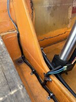
If your hatch doesn't have an accessible pin on the actuator there are a couple things you can do, if you have a cigarette lighter you can use a cigarette lighter charger. You can also make up a jumper cord that you can connect a regular charger to and run it lower than 10a
If you have easy access to your dash wiring you can clip a jump to any main hot and ground and back feed power into the system with a jumper box, or battery charger.
You can install actual jumper posts into your rear seat base (Halletts that the batteries under the seat base have these standard)
Many times the hatch pins can be difficult and it's just easier to jumper power into the system.

")